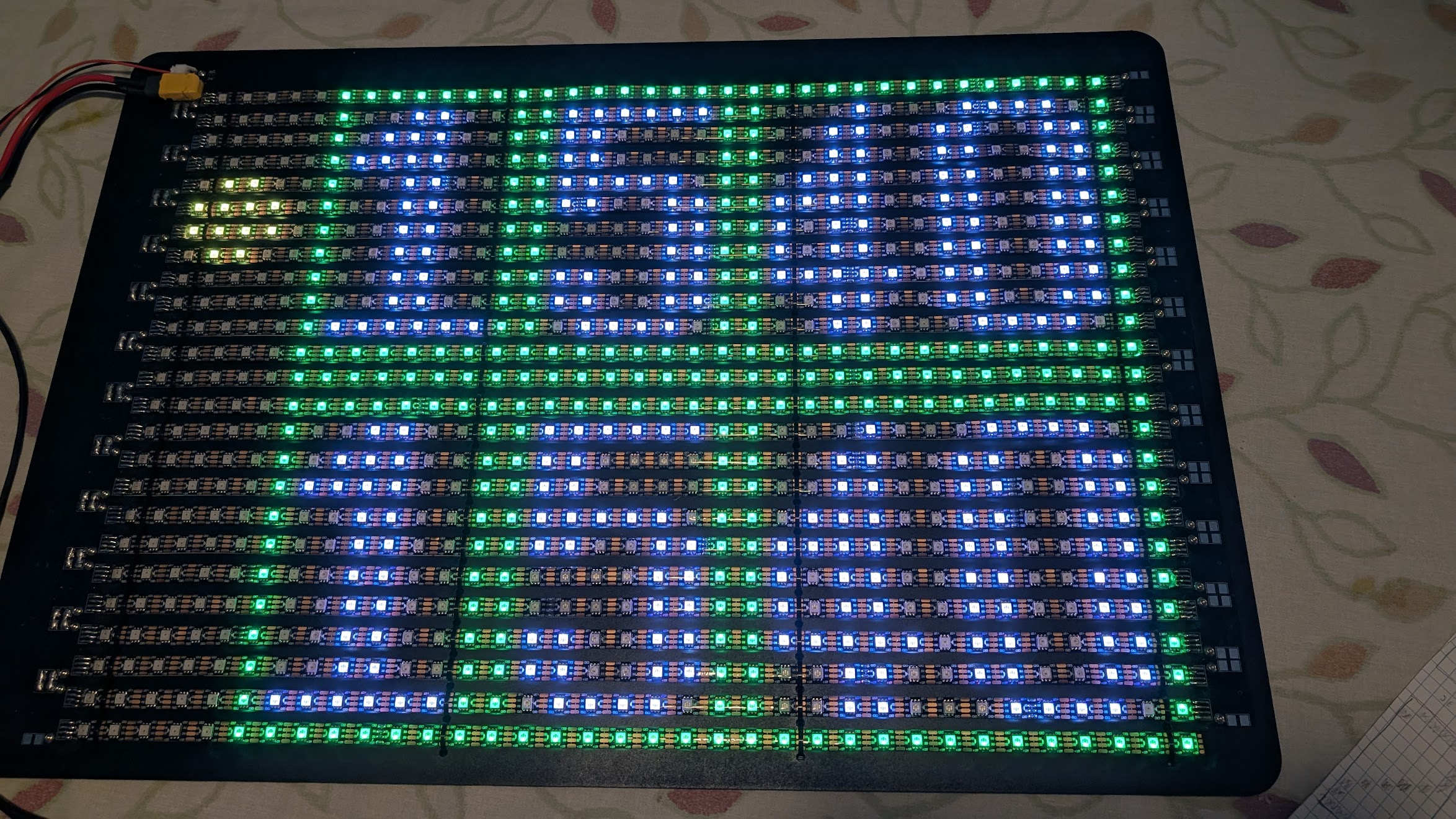
This project started by request from my dad, who has his own grass tennis court on his property in the United Kingdom. As part of the growing community using his court, he has begun to run matches and tournaments, and found that his traditional flip-book scoreboard was becoming a bottleneck for playtime. We explored potential ways using existing products such as TVs, however these badly suffered from glare in outdoor sunny environments, and were also rather expensive, so we decided to explore building our own.
Requirements
Due to the simple nature of the graphics we wanted to display, the resolution of the display did not have to be very high, but it did have to be very bright, have high color range and high contrast. The display also should be able to be powered by a 36V battery pack. The intention was to control the display with some wireless device such as a raspberry pi or an ESP32 dev board. The simplest way to control LEDs with these are with Worldsemi Addressable LED strips. These LED strips allow a large number of color LEDs to have their color and brightness configured through a single signal wire (with two power supply rails of course). These LED strips can be arranged in a snaking pattern to allow one connected strip to act as a grid of controllable LEDs.
Component Selection
There are a number of addressable LED types available, but the two most commonly used which allow full control over each LED induviudally are WS2812B, and WS2815. The key differences between these two, are WS2812B operates at 5V, whereas WS2815 operates at 12V with a backup data channel. WS2812B is commonly used for household lighting as it can be powered by a USB power supply (5V). A higher operating voltage means lower current for the same power output, so WS2815 was the best option for this use case, it would also mean less load on the 5V supply required to run the supporting electronics. We also decided that for ease of design, we would use a complete ESP32 dev board as opposed to building our own microcontroller circuit which would be much more expensive.
Circuit Design
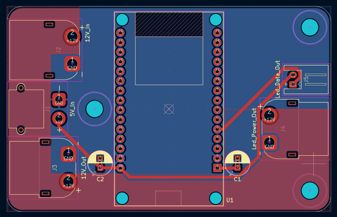
The majority of the PCBs I designed for this project serve only as power and signal routing organisation. The main board has a slot for the ESP32 dev board to be soldered on, and a number of cable connectors for routing power to the step down converters, and to the LEDs. To supply the 12V and 5V rails, there is a buck converter between the 36V battery and the 12V input, and a buck converter between the 12V output and 5V input.
The largest concern when designing this scoreboard was how to connect the ends of adjacent rows of the LED matrix. In theory the cheapest and simplest solution would be to solder wires between the pads, however this would be rather slow to assemble as every connection would require 4 different lengths of wire to be cut and have the ends stripped. This method also does not have any power injection, meaning the supply voltage level by the end of the matrix would be lowered due to series resistance.
| Connector Board | Entry Board |
|---|---|
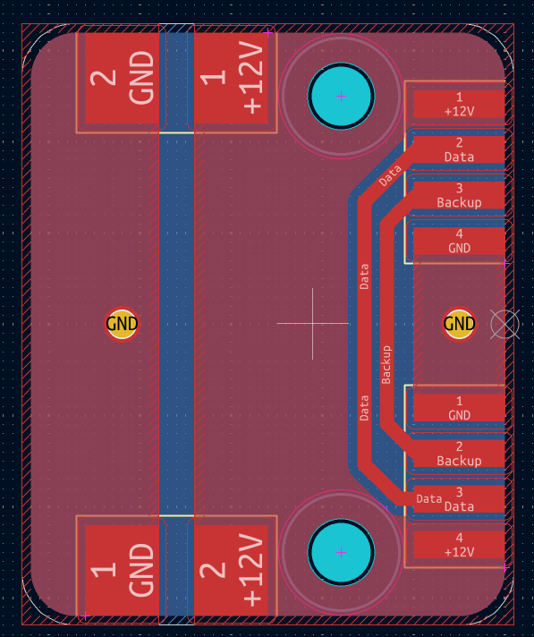 | 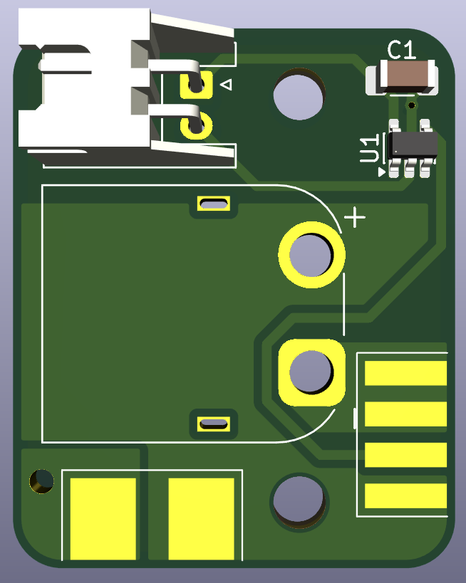 |
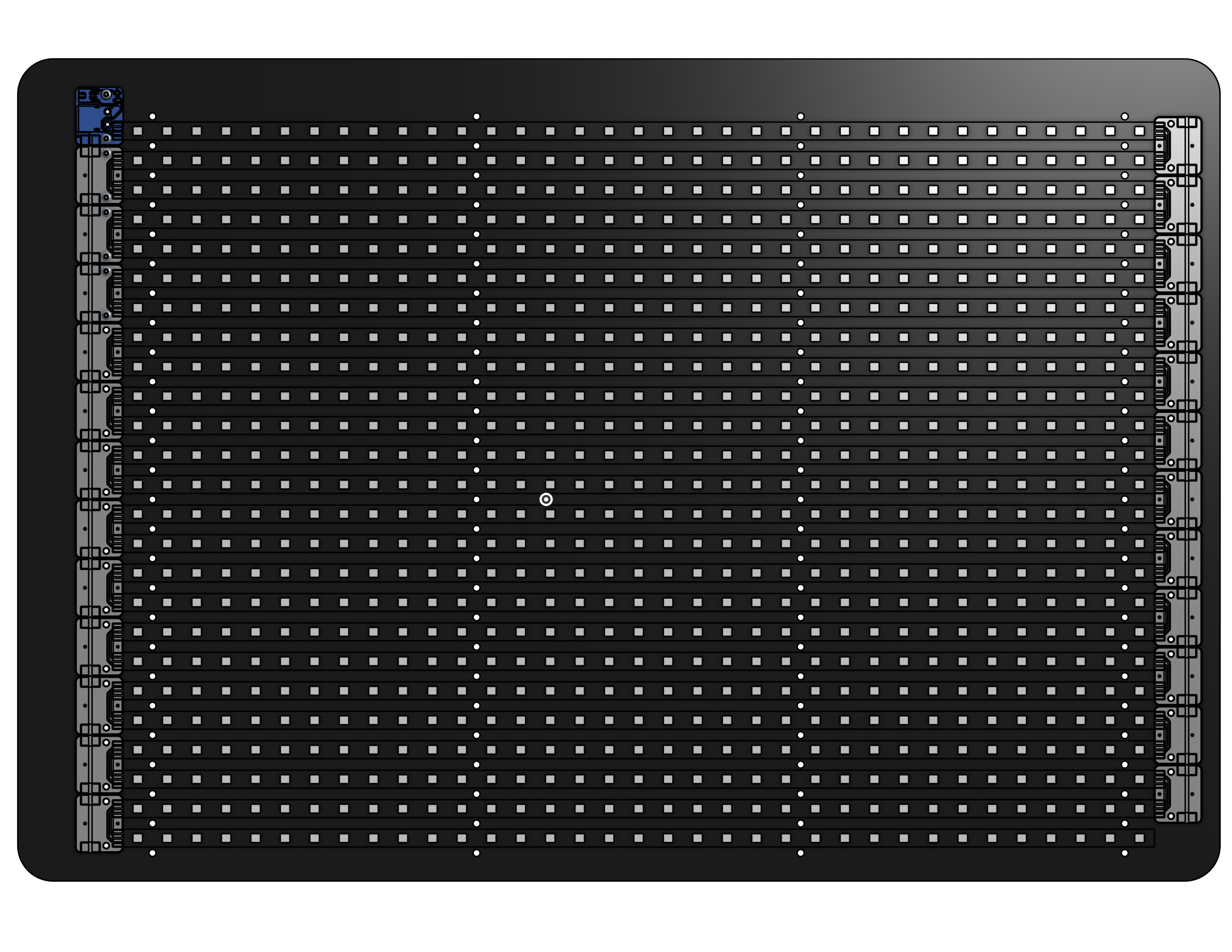
To make assembly easier and have power injection, I designed two types of boards which could be spaced out specifically and soldered to the LED strips to achieve an equally spaced square grid layout. The boards have holes for M3 screws, which allows for automatic alignment when attached to a specific lasercut backboard. A mockup of the scoreboard in CAD is shown in the figure below.
Building it
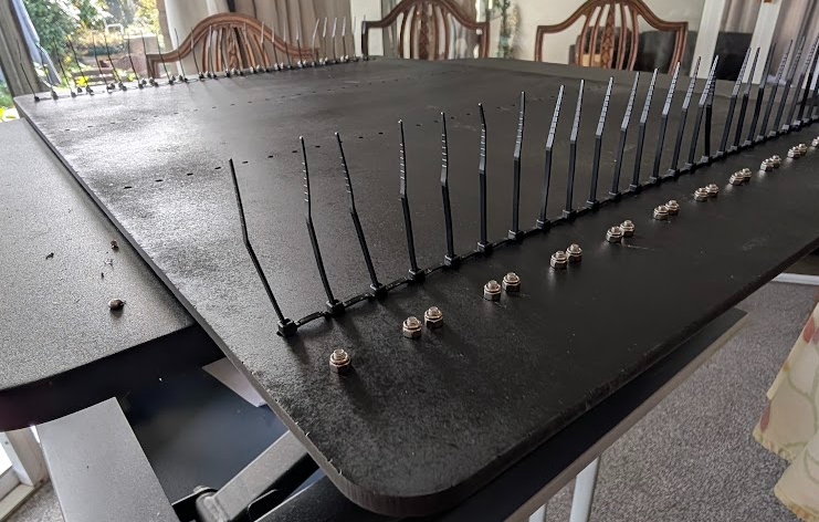
Keeping the LEDs correctly grid aligned would be rather difficult to do by hand, so I built in holes for zipties into the backboard sketch. The backboard is made out of 6mm lasercut MDF, which was then spraypainted back to aid in contrast and protect the material from moisture. When we started assembling the circuit boards (which were manufactured by JLCPCB) onto the backboard, we discovered that the solder was not happy to bridge between adjacent boards as we had hoped. To work around this we employed a combination of short wire cores to act as bridges, and a technique where the soldering iron would be kept in the solder long enough for the flux to fully burn off, making the solder more goopy, and easier to pull across.
Programming it
This part of the project is still a work in progress. The firmware for the ESP32 controller is written in Rust. I prefer to write in Rust over C++ when possible due to its improved memory safety and extensive tooling. To control the LEDs, I used a library which makes use of the ESP32s SPI peripheral to mimic the WS28125 control signal. Using this library made it very easy to get the display up and running, however I did have to write my own logic for converting pixel coordinates into strip coordinates. The next steps for this project will be developing full remote control (over wifi or bluetooth) capabilities and some form of match or tournament tracking system.